I have encountered examples of using the forward stock rubber mounts, but hard mounting the rear. I think that is a really bad idea. The motor generates alot of torque, plus the car goes over bumps. This will tend to flex the rubber mounts, and also flex the metal of the hard mounts. Lots of flex cycles on a hard mount can eventually break it. It is better to either hard mount everything, or rubber mount everything. I decided to leverage the brilliant Porsche engineers expertise, and use the stock rubber mounts.
You can see the original Porsche 911 motor mount here:
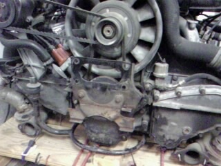
Porschephiles might have spotted the motor mount is flipped above the rubber mount points, rather than below like it does with the gasoline car. I did this so the motor mount bracket would not interfere with battery boxes. I think there is enough clearance, but I'll have to watch it and put in some washers if the rubber flexes too much and lets metal hit metal. Note how complicated the old gas motor is! The new electric motor is also much smaller, it is about the diameter of the fan of the gas motor, even though it'll put out comparable power and double the torque of the old gas motor.
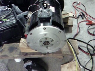
I need to bolt to the outermost 8 bolts. They screw into the strong outer motor case. I didn't want to use the inner bolts, as it appears they attach the motor brush gear. The center part is raised, so my plate will need a big hole to clear this.
This is the plate that will attach to the back of the motor. The "B" holes are optional, and are made if both plates are stacked to machine them together. Click the blueprint for a bigger picture.

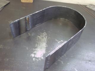
This is the spacer that goes between the motor plate and the mount plate. The width of the plate depends on the motor length and the adapter length. It needs to be curved to clear the motor bolts, and to clear the raised portion on the back of the motor. I used a ring roller to do a smooth curve rather than doing a series of bends.
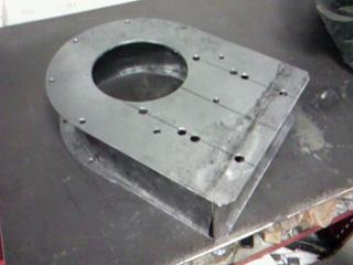
This plate attaches to the original Porsche 911 motor mount. The bottom four holes are to attach the mount in the stock location. The top four holes flips the motor mount, and frees up room for battery boxes. The oval hole is to allow backside access to put in and tighten bolts.
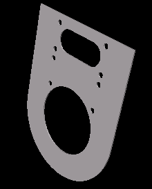

If you are sure you don't need the room you could shorten the mount to leave off the top four holes. This would put the gas motor's mount in the stock position.
This is the top plate, just a flat rectangle. The 3D picture was pretty boring, so I left it off.
The blueprints were done with the free software from http://www.emachineshop.com . You can then electronically submit your design, and they'll mail it back to you in about 1 month. The software also automatically prices your part. For this case, for a quantity of 1, the prices were:
$541.18 motor plate emachineshop cost
$532.55 mount plate emachineshop cost
$218.27 spacer emachineshop cost
------------
$1292.00 sum
In my case, since I'm making these parts myself, the cost is much lower than this, even if I "paid" myself a decent wage per hour. It is nice to feel like I'm saving myself about $1200. This also justifies my lathe/mill and welder -- these tools will have paid for themselves several times over by the time my car is done.
Video of plasma cutting
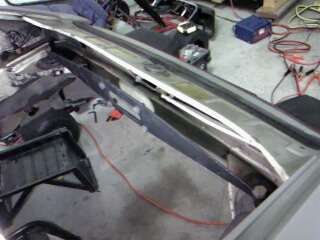
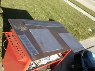
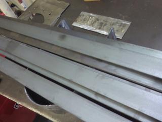
The motor plate, mount plate, spacer, and top plate in their raw form:
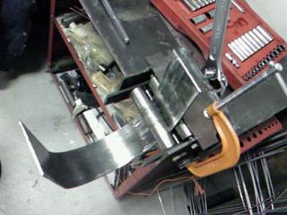
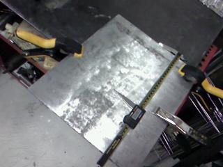
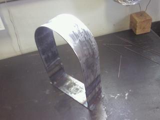
This device is called a "ring roller." I built it myself. This picture and the next few show how the metal gets bent into a gentle curve.
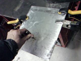
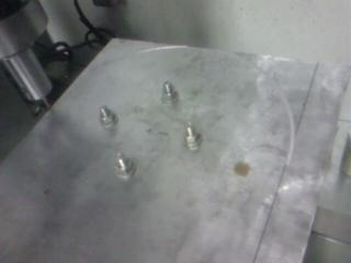
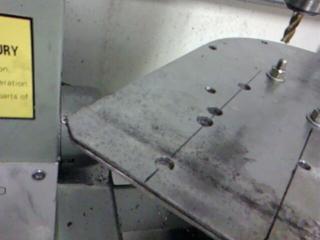
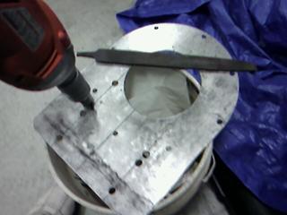
This neat punch is spring loaded, so when you push hard it suddenly snaps and puts a small divot into the metal. This gives the drill a good starting point so it doesn't walk around. These first four holes are drilled with a hand drill. They do not need to be accurate, as they are only used to hold the part to the rotary table, and will be cut out of the final piece.
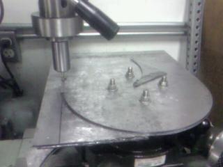
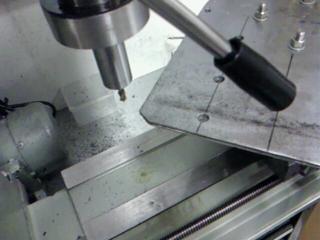
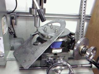
I could have left the motor plate and mount plate rectangular. It wasn't much more trouble to round it off, though, as I was already using the rotary table to accurately drill the motor mount holes. This saves a little bit of weight and looks cool. Turning the rotary table under the mill bit cuts this curve.
I ran the part back and forth (towards and away from you in this picture), until the spacing from the mill bit was constant. This squared the part with the x-y motion of the machine.
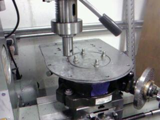
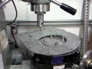
Once I was squared up, I put a piece of tape on the rotary table, and marked the 00 degree angle. This made it easy to get square to an edge, or to turn to the correct angles for the 8 motor bolt holes I needed to drill.
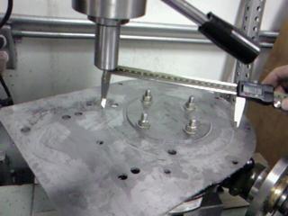
Measuring and marking hole locations.
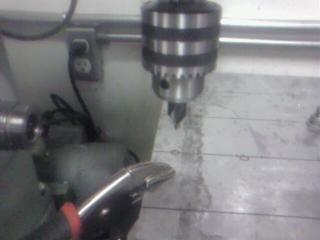
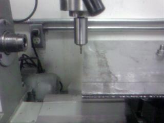
Using a center drill for a pilot hole. The center drill is very stiff and keeps things on center. Even in a drill press, a regular drill bit is surprisingly flexible and can drill off center, without a pilot hole.
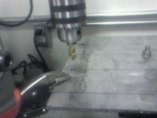
Once a pilot hole is drilled, then a regular drill bit is used. I had to shorten this drill bit with a cutoff wheel to get it into the chuck, since using the rotary table limits my clearance.
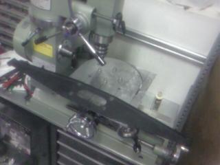
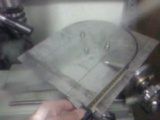
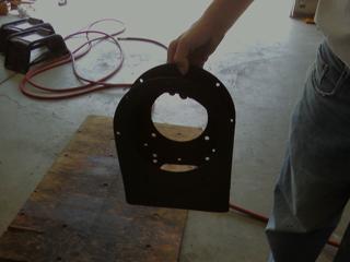
The black thing is the original gas engine motor mount that I'm reusing for the electric motor. I'm mighty glad I checked my markings, as they were off! Even though the four holes look rectangular, actually 2 of the bolts are further apart than the other 2.
This shows how the bolt holes that looked to be visually lined up on the motor mount actually weren't in a line. The closer pair of holes would be to use the gas engine motor mount in the original lower location. The further pair of holes are for flipping the gas engine motor mount to above, which makes more room for batteries.
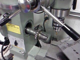
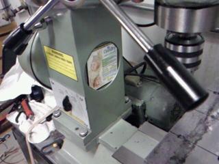
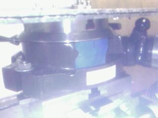
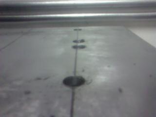
The lathe spindle was in the way of the milling operations, so I took it out. It only took about 3 minutes to get it out. Notice how huge the bearing on it is, it is bigger than the wheel bearings on a car. Removing the lathe spindle left a huge hole in the machine, just begging for metal bits to fly in there and short out the electronics. I covered it with a refrigerator magnet that I needed to trim slightly. It worked great!
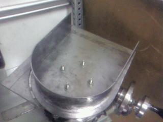
Now you see why the corners were trimmed -- to allow the part to rotate 360 degrees, so holes could be drilled and circles cut. My machine was just barely big enough to make this part without rebolting it. You generally want to keep the part bolted to the rotary table the whole time, so you don't lose your reference. It's very difficult to accurately bolt a part back to its exact original position.
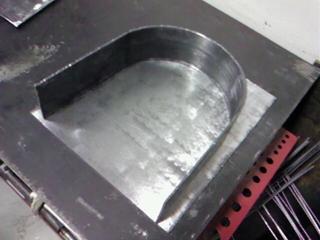
The two plates were stacked and machined together. The plate with the smaller hole was cut off first, so gouging into the lower plate would just gouge metal that was about to be cut away anyways. Yay, the mount plate is free!
I lightly kissed the plate with the mill, and then checked the circle would be the right size before making irrevocable cuts. Yay, the 2nd plate is free!
Rough edges were lightly filed, and holes lightly beveled, to make the plate safer to handle and so it would lay flat.
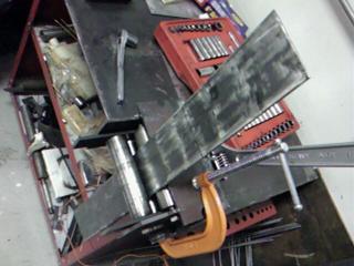
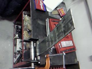
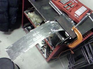
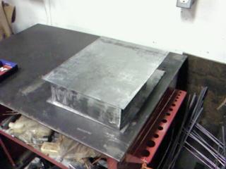
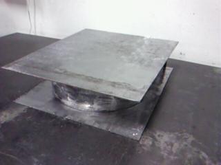
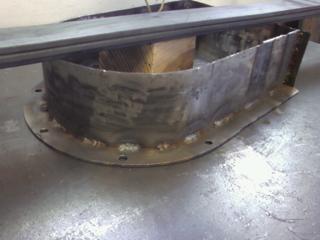
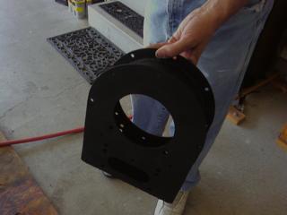
Here's a quick stack and preview of the final product configuration. The middle U shaped spacer needs to be ring rolled some more to a tighter curve.
Unfortunately, my U spacer was a little bit too short, so I welded on these plates to make it long enough. A perfectionist would have remade the part.
The U spacer had a slight warp to it, so I weighted it down with some steel to make it lay flat while I tack welded things.
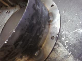
The U spacer welded to the top plate (shown on the bottom in this pic, but is on the top in the car).
First I did tack welds about every four inches (10 cm), and then did short welds in between the tack welds.
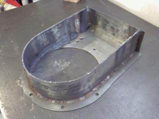
Then I did welds between those welds, and finally did welds between those welds, making a continuous weld bead. Doing welds this way helps prevent warping.
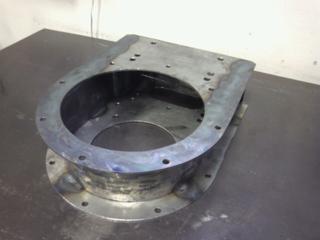
The mount plate was welded similarly.
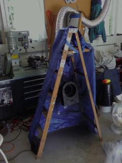
Since the weather was cold, I made a little painting booth with a ladder and tarps. At the lower left of the ladder is a space heater. The silver hose is for fume venting.
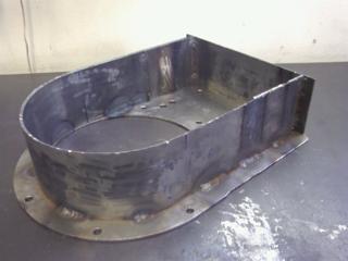
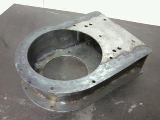
The finished product! You can see some pics of this motor mount on the electric motor and going into the car here: http://ExplodingDinosaurs.com/9electric/motorinstall .
You can see more of my car adventures at my main page:
http://ExplodingDinosaurs.com